Add it to your cut list, or continue with the pieces and files already included.
CUT TO YOUR DIMENSIONS
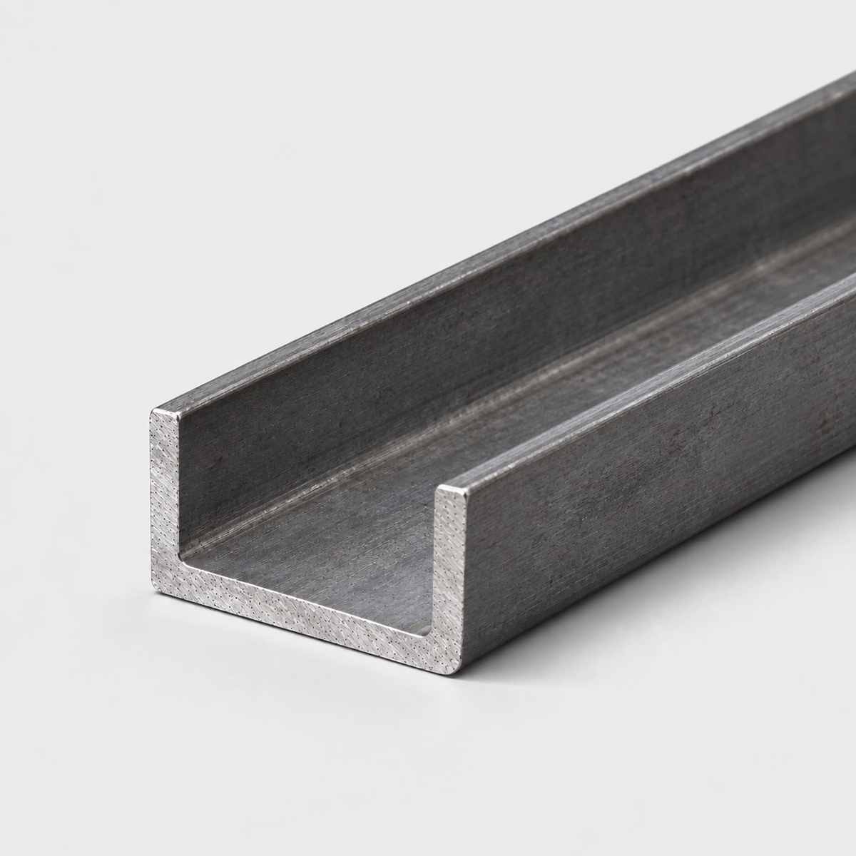
CARBON STEEL / CHANNELIllustrative material image
LIVE DIMENSION VIEWCHANNEL
Carbon Steel Channel
See your specification take shape.
Dimension labels are on. Enter dimensions to see their labels.
MADE FOR YOUR CUT LIST
The right metal. Your exact dimensions.
From a single part to a mixed-material project. Configure each cut, then bring it all together in one reviewed quote.
Custom cut sizesMultiple parts, one requestReviewed specifications
CUT-TO-SIZE METAL
Carbon Steel Channel
Request carbon steel channel with a section designation or detailed drawing. Specify outside height, flange width, length and the actual web and flange geometry.
Attach a PDF, DXF or STEP file. You can request a review without configuring individual pieces.
How your quote works +
Add one or more cuts, share your requirements and tell us where to deliver. We review material, cutting and freight before sending a quote.
Dimensions & material weight +
Dimensions describe your requested section and cut length. Standard sections and feasible cuts are confirmed during review. Include any tolerance in project details. Weight is theoretical, uses ideal section geometry and excludes corner radii, packaging and cutting loss. The preview is a schematic, not a manufacturing drawing.
PROJECT CONTENTS
Your cut list
Cut lines are saved in this browser. Only added pieces are included in your request.
What to include in your request
A rolled structural channel can differ from the builder's uniform U profile. Use the drawing or section designation as the controlling reference.
Subject to review; no live-stock or tolerance guarantee
Ideal uniform-thickness section. Weight excludes root radii, tapered flanges and tolerances. Requested dimensions do not imply arbitrary sections can be manufactured.
01
A channel opening creates access and fit tradeoffs
A channel surrounds space on three sides while leaving one side open. That opening can permit insertion or access that a closed rectangular tube does not provide, but it also creates a different interface for adjoining parts. A component resting against the web may need clearance from the flanges and their transitions. The useful internal envelope therefore differs from the outside outline, and the opening direction becomes part of how the finished assembly is built and used.
02
Distinguish clearance from deliberate edge geometry
A part placed inside a channel may need clearance along the flanges but contact against the web. Treat those functions separately when defining the interface. Similarly, removing a burr at an opening is not the same as creating a specified lead-in chamfer for an inserted component. A section through the joint can show both requirements clearly. This is more useful than describing the entire internal surface as smooth without explaining how the mating part enters or locates.
03
Build an inspection plan around the intended fit
When a channel receives another component, identify the functional internal envelope and the surfaces that are only clearance boundaries. State which features will be finished later and which need to be accepted on the incoming material. For several similar channels in one assembly, use separate part identifiers and an opening-direction note. This keeps a correct section from being installed backward or assigned to the wrong location simply because the pieces share an overall size.
Compare channel with neighboring profiles
Compare channel with neighboring profiles
Catalog option
Profile arrangement
What needs a separate decision
Carbon steel channel
Open section with web and flanges
Actual section geometry and opening direction.
Carbon steel angle
Two connected legs
A different interface and attachment layout.
Carbon steel rectangular tube
Closed hollow rectangle
Access and connections for a closed profile.
PUT THE DIMENSIONS INTO PRACTICE
Example: a four-piece channel request
Use this illustrative cut line to see how the fields work. It is a dimensional example, not a stock listing or a recommended section for a particular load.
Flange width1 in25.4 mm
Outside height2 in50.8 mm
Uniform thickness0.125 in3.175 mm
Cut length24 in609.6 mm
The model uses a 2 in outside height, 1 in flange width and 1/8 in uniform thickness. Its ideal area is t × (2b + h − 2t), or 0.46875 square inches. A channel with tapered flanges or a different web thickness requires its actual section data.
How the theoretical weight is calculated
Cross-sectional area × cut length × reference density = estimated material weight.
Material in this example
Carbon steel
Reference for this example
Material average; grade to be specified
Density used
7,850 kg/m³
One piece, approximately
3.19 lb / 1.45 kg
Four pieces, approximately
12.76 lb / 5.79 kg
Calculated from ideal geometry and a reference density. Actual section, alloy, tolerances, cutting loss and packaging can change the result. This is not a shipping weight or a load rating.
On your own cut list, add a part reference and quantity to each distinct size. Put extra operations such as holes, miters, threads or finish work on the drawing, then keep that drawing reference with the relevant line.
Can a structural C-channel be described by one thickness?
Often that is insufficient. Web and flange thicknesses, taper and root radii may differ. Attach the full section designation and dimensions rather than relying on the simplified preview.
Is a bent steel U-channel equivalent to a rolled channel?
Do not assume equivalence. Geometry, radii, material condition and section properties can differ. Confirm any proposed substitution against the drawing.
Can I calculate allowable channel span from its weight?
No. Span capacity requires the section properties, material, loads, bracing and connections. The material-weight estimate does not provide a structural rating.
What are the web and flanges of a channel?
The web is the connecting portion between the two projecting flanges. These names distinguish the section's surfaces when discussing attachment or fit. A hole in the web and a hole in a flange can serve different interfaces even though both belong to the same member.
Why is a channel's usable inside space different from its outside size?
The walls and their transitions occupy part of the outside envelope. A mating component must fit the remaining space and any local features along its path. The outer height and width therefore do not directly describe every clearance available inside the actual channel section.
What practical difference does an open channel make compared with rectangular tube?
The open side changes how a component or tool can enter the section. A closed tube encloses that region, while a channel leaves an approach from one side. This is an access and interface distinction; it does not establish equivalent structural behavior between the two profiles.
Why might a part contact a channel web before it contacts the flanges?
The interface may intentionally use the web as its locating surface while leaving clearance at the sides. That arrangement assigns different jobs to the section's surfaces. Equal contact everywhere is not automatically the goal; the component design determines which relationships establish its installed position.
How can I distinguish similar channels in a receiving list?
List the part number, actual section reference, blank length, quantity, and opening orientation where relevant. Link each item to the current drawing revision. If the raw pieces are identical but the finished features differ, preserve that distinction in the manufacturing documentation.
What information helps replace an old channel-shaped part?
Provide a verified section drawing, material requirement, connection details, and the installed orientation. Mark uncertain measurements from the old part so they can be resolved before purchase. A photograph may show the arrangement but rarely establishes the internal fit or the exact section geometry.
What dimensions do I need to request carbon steel channel?
Provide flange width, outside height, uniform thickness, cut length, plus quantity for each size. Use inches or millimeters consistently. Add the required grade, condition, finish and any critical tolerances; attach a drawing for details the standard fields cannot describe.
Turn your specification into a clear request.
Include the material, dimensions, quantity and critical requirements. Availability, supplied condition, cutting and delivery are confirmed in a reviewed quote.