Add it to your cut list, or continue with the pieces and files already included.
CUT TO YOUR DIMENSIONS
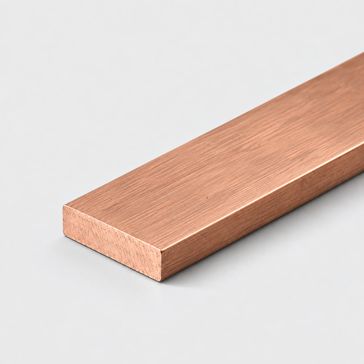
COPPER / FLAT BARIllustrative material image
LIVE DIMENSION VIEWFLAT BAR
Copper Flat Bar
See your specification take shape.
Dimension labels are on. Enter dimensions to see their labels.
MADE FOR YOUR CUT LIST
The right metal. Your exact dimensions.
From a single part to a mixed-material project. Configure each cut, then bring it all together in one reviewed quote.
Custom cut sizesMultiple parts, one requestReviewed specifications
CUT-TO-SIZE METAL
C110 Copper Flat Bar
Specify C110 copper flat bar by thickness, width and length. Add the engineered section, hole pattern, finish and documentation requirements for your component.
Attach a PDF, DXF or STEP file. You can request a review without configuring individual pieces.
How your quote works +
Add one or more cuts, share your requirements and tell us where to deliver. We review material, cutting and freight before sending a quote.
Dimensions & material weight +
Dimensions describe your requested section and cut length. Standard sections and feasible cuts are confirmed during review. Include any tolerance in project details. Weight is theoretical, uses ideal section geometry and excludes corner radii, packaging and cutting loss. The preview is a schematic, not a manufacturing drawing.
PROJECT CONTENTS
Your cut list
Cut lines are saved in this browser. Only added pieces are included in your request.
What to include in your request
For electrical components, supply the required section and connection drawing. The configurator does not select or rate a busbar assembly.
Material
Copper
Profile
Flat Bar
Grade references
C110 — confirm grade and condition in the quote
Dimensions
Thickness, width, cut length
Units
Inches or millimeters; decimals or fractions
Supply & cutting
Subject to review; no live-stock or tolerance guarantee
Theoretical geometry only. Actual dimensions, tolerances and cutting require supplier review.
01
Cross-section and contact area describe different geometry
The cross-section of a flat bar is viewed across its length, while a contact area may lie on one of its broad faces. An overlapping connection uses part of that face and introduces holes, hardware, and surface requirements that do not appear in the plain rectangular section. Two blanks with the same cross-section can therefore become quite different components. The C110 material description identifies the starting copper, while the completed connection remains a separate engineered arrangement with its own interfaces.
02
Identify contact surfaces and coating boundaries
A copper bar may contain contact pads, concealed spans, and visible regions with different requirements. Mark those areas on the drawing rather than applying one undifferentiated finish note to the entire piece. If your design calls for a surface treatment, define its boundaries and the stage at which final dimensions are accepted. This is particularly useful around bolted interfaces, where a clear section drawing can distinguish the material blank from the finished surface and attachment arrangement.
03
Use the assembly layout to organize the cut list
Several bars in one assembly may share a section while differing in hole pattern, orientation, or bend geometry. Give each finished component a unique identifier and connect it to the layout. Where your shop will perform later operations, show the raw blank separately from the completed part. A coordinated cut list then becomes a purchasing tool rather than a substitute for the design, and similar-looking pieces remain traceable to the locations for which they were specified.
Compare copper starting geometries
Compare copper starting geometries
Catalog option
Form
Useful distinction
C110 copper flat bar
Rectangular solid
A strip-shaped blank with defined broad contact faces.
C110 copper sheet
Broad flat blank
A separate product form for the specified component outline.
C110 copper round bar
Circular solid
A different starting envelope for a separately designed part.
PUT THE DIMENSIONS INTO PRACTICE
Example: a four-piece flat bar request
Use this illustrative cut line to see how the fields work. It is a dimensional example, not a stock listing or a recommended section for a particular load.
Thickness0.25 in6.35 mm
Width2 in50.8 mm
Cut length12 in304.8 mm
The section is 1/4 × 2 in and the cut length is 12 in. The ideal cross-sectional area is 0.5 square inches, so one blank contains 6 cubic inches of material. Keep thickness and width labeled when communicating the cut list.
How the theoretical weight is calculated
Cross-sectional area × cut length × reference density = estimated material weight.
Material in this example
Copper
Reference for this example
C110 grade reference
Density used
8,910 kg/m³
One piece, approximately
1.93 lb / 0.88 kg
Four pieces, approximately
7.73 lb / 3.50 kg
Calculated from ideal geometry and a reference density. Actual section, alloy, tolerances, cutting loss and packaging can change the result. This is not a shipping weight or a load rating.
On your own cut list, add a part reference and quantity to each distinct size. Put extra operations such as holes, miters, threads or finish work on the drawing, then keep that drawing reference with the relevant line.
Can the configurator tell me the ampacity of copper flat bar?
No. It estimates material weight. Electrical rating depends on the complete design, installation, temperature limits and connections; provide the engineered material specification.
Does a copper flat-bar request include drilled connection holes?
No. Attach the hole pattern, tolerances and any plating or contact-surface requirements so the additional scope can be reviewed.
Is C110 flat bar automatically a finished busbar?
No. C110 is a material reference, while a finished busbar also has geometry, connection, surface and application requirements. Define those on the drawing.
What is the difference between copper bar cross-section and a contact pad?
Cross-section describes the material envelope across the bar's length. A contact pad is a designated region where the finished component meets another part, often on a broad face. The two areas describe different geometry, so one cannot be used as a direct description of the other.
Why does a hole pattern need to relate to the contact region?
The holes position the fastening arrangement relative to the surfaces that are intended to meet. Correct hole diameters alone do not establish that relationship. A finished connection therefore depends on the location of the pattern as well as the definition of the adjoining contact faces.
Is a smooth-looking copper surface the same as a flat contact face?
No. Smooth appearance concerns surface texture, while flatness concerns the overall form of the face. The two can vary independently. A finished contact interface may therefore have separate requirements for geometry and surface condition rather than one general description such as bright or polished.
Why does a formed copper bar need a different outline from its flat blank?
Bending changes the path of the material, creating offset faces and connection locations in three dimensions. The starting blank and the finished assembly envelope therefore describe different stages of the part. The connection drawing determines the final arrangement; a raw cut length does not define it.
What details matter for a bolted overlap between two bars?
Provide the engineered connection drawing with overlap geometry, hole locations, contact regions, and the specified hardware arrangement. Reference those features from consistent datums on both parts. This explains the interface directly without treating two matching rectangular blanks as a complete connection design.
Can a copper bar request include both prototype and production pieces?
Yes. Separate the quantities and identify any differences in drawing revision or acceptance requirements. Keep development blanks distinguishable from released components, especially if the hole pattern or layout may change. This makes the material request useful without presenting an exploratory design as a finished production specification.
What dimensions do I need to request c110 copper flat bar?
Provide thickness, width, cut length, plus quantity for each size. Use inches or millimeters consistently. Add the required grade, condition, finish and any critical tolerances; attach a drawing for details the standard fields cannot describe.
Turn your specification into a clear request.
Include the material, dimensions, quantity and critical requirements. Availability, supplied condition, cutting and delivery are confirmed in a reviewed quote.