Channel profiles. Make the section clear.
Explore open channel profiles in aluminum, carbon steel and stainless steel. The configurator models a U section with a uniform wall for specification review.
Selection guide & common questions ↓Choose your channel material
3 matching products · Open a product to configure your dimensions.
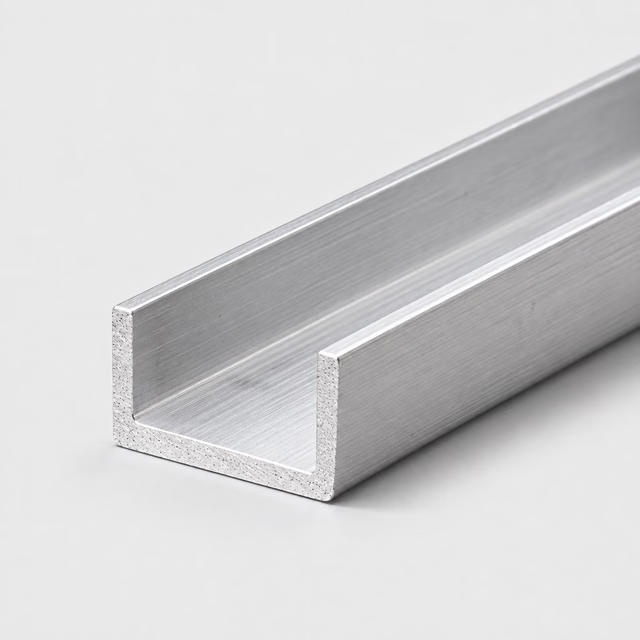 ↗
↗Aluminum Channel
6061 / 6063
Choose dimensions & quantity →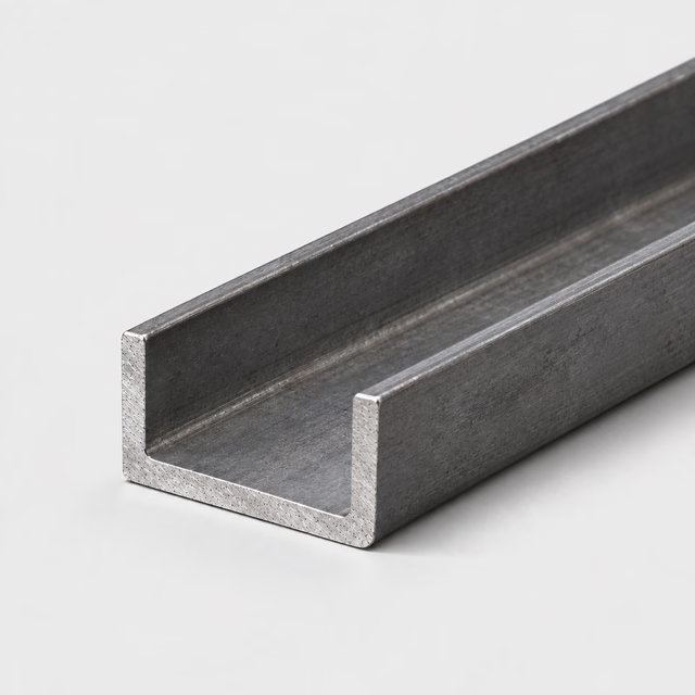 ↗
↗Carbon steel Channel
Grade to be specified
Choose dimensions & quantity →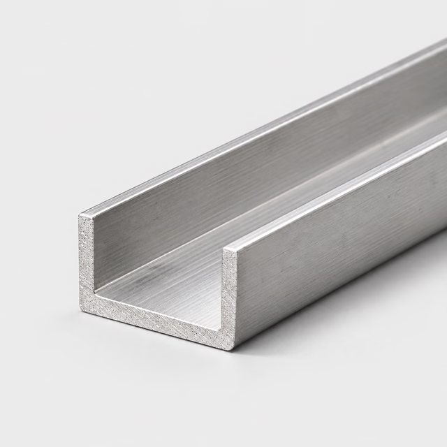 ↗
↗Stainless steel Channel
304 / 316
Choose dimensions & quantity →This range describes material and profile combinations available to request. It does not represent live stock, confirmed grades, cutting capacity or delivery dates.
Real channels can have different web and flange thicknesses, tapered flanges and root radii. The simplified U-shaped preview does not describe every structural channel. Attach a section drawing or full designation whenever the single-thickness model is insufficient.
- Enter outside height, flange width, uniform thickness and length where applicable.
- For nonuniform sections, provide the full designation and a drawing.
- Specify the clear opening and internal radii if a part must fit inside.
Web, flanges and opening describe different features
The web is the connecting back of a channel; the flanges extend from it to form the sides. Together they create an open section with an interior space. The outside envelope, flange geometry and clear opening answer different assembly questions. A part sitting inside the channel depends on that opening and the local corner geometry, while a part mounted outside may use the web as its reference. Naming these features makes a section drawing easier to read than describing every dimension as width.
An open side changes access
A channel leaves one side accessible along its length, unlike an enclosed tube. That can be useful when installing a backing component, reaching a fastener or accommodating another part within the section. The opening also becomes part of the visible and functional arrangement, so its direction matters. An open profile is not simply a tube with an equivalent outline: it creates different interfaces and design considerations. Choose it because the accessible geometry suits the assembly, then evaluate the finished member's requirements.
Organize guides and rails as controlled parts
For a project using several channel lengths, assign part IDs and connect them to the layout drawing. Indicate orientation, supplied length and quantity for each distinct piece, especially where left and right positions have different later operations. If the inside surface is visible or interacts with another component, describe the requirement clearly. Treat finish, identification and grouping as separate notes. A controlled list makes it easier to compare offers and update a layout without losing individual part requirements.
Read the channel section by feature
| Feature | What it describes | Why a buyer cares |
|---|---|---|
| Web | The connecting back of the section | Can establish a mounting or reference face |
| Flanges | The sides extending from the web | Define interfaces and access around an inserted part |
| Clear opening | Usable interior space | Matters more than the outside name for a mating component |
| Open-side orientation | Direction of access along the section | Changes installation, fastener access and appearance |
Example: a four-piece channel request
Use this illustrative cut line to see how the fields work. It is a dimensional example, not a stock listing or a recommended section for a particular load.
The model uses a 2 in outside height, 1 in flange width and 1/8 in uniform thickness. Its ideal area is t × (2b + h − 2t), or 0.46875 square inches. A channel with tapered flanges or a different web thickness requires its actual section data.
How the theoretical weight is calculated
Cross-sectional area × cut length × reference density = estimated material weight.
- Material in this example
- Aluminum
- Reference for this example
- 6061 grade reference
- Density used
- 2,700 kg/m³
- One piece, approximately
- 1.10 lb / 0.50 kg
- Four pieces, approximately
- 4.39 lb / 1.99 kg
Calculated from ideal geometry and a reference density. Actual section, alloy, tolerances, cutting loss and packaging can change the result. This is not a shipping weight or a load rating.
On your own cut list, add a part reference and quantity to each distinct size. Put extra operations such as holes, miters, threads or finish work on the drawing, then keep that drawing reference with the relevant line.
Calculate the weight of your own dimensions →Questions about channel
Is a U-channel the same as every C-channel?
No. Channel naming can cover different section geometries. Use the actual dimensions or a recognized section designation and drawing.
How do I request a channel with tapered flanges?
Attach the section specification and identify web and flange dimensions separately. A single uniform thickness cannot fully describe that profile.
Can the flange width field specify the clear inside opening?
No. It describes the flange dimension in the model. If inside clearance is critical, give the clear-opening requirement and interface drawing explicitly.
What should I provide if a component must sit inside the channel?
Include the component drawing or interface dimensions and identify the clearance it needs. Add a labeled channel end view rather than relying on outside dimensions alone. Explain whether the part slides, rests or is fixed in place so the responsible team can define the relevant fit.
What is the web of a channel?
The web is the connecting back that joins the two flanges. It may serve as a mounting surface or define one side of the interior space. Labeling the web and flanges on an end view helps clarify where holes, contacts or visible surfaces belong.
Why choose a channel rather than a closed rectangular tube?
A channel gives access through its open side, which can help with internal attachments or components placed inside the section. A closed tube has a different geometry and different design behavior. Choose based on the actual interfaces and design requirements rather than treating matching outside dimensions as equivalence.
Does turning a channel around change the useful space in an assembly?
The section's own dimensions remain the same, but the opening, mounting face and access move relative to surrounding parts. A fastener or inserted component may then become inaccessible or interfere with another surface. Show the installed orientation so the purchasing and fabrication views describe the same arrangement.
How should I compare a channel offer with my drawing?
Check the material callout, profile geometry, supplied length and quantity, then review the mating and mounting interfaces shown on the drawing. Compare included operations and any finish requirements separately. Resolve differences before accepting the offer so a familiar section name does not conceal a different scope.
Turn your specification into a clear request.
Include the material, dimensions, quantity and critical requirements. Availability, supplied condition, cutting and delivery are confirmed in a reviewed quote.