Add it to your cut list, or continue with the pieces and files already included.
CUT TO YOUR DIMENSIONS
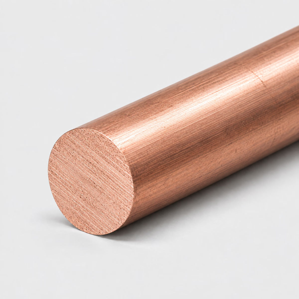
COPPER / ROUND BARIllustrative material image
LIVE DIMENSION VIEWROUND BAR
Copper Round Bar
See your specification take shape.
Dimension labels are on. Enter dimensions to see their labels.
MADE FOR YOUR CUT LIST
The right metal. Your exact dimensions.
From a single part to a mixed-material project. Configure each cut, then bring it all together in one reviewed quote.
Custom cut sizesMultiple parts, one requestReviewed specifications
CUT-TO-SIZE METAL
C110 Copper Round Bar
Request solid C110 copper round bar for cylindrical machining blanks. Specify stock diameter, cut length, condition and any required material documentation.
Attach a PDF, DXF or STEP file. You can request a review without configuring individual pieces.
How your quote works +
Add one or more cuts, share your requirements and tell us where to deliver. We review material, cutting and freight before sending a quote.
Dimensions & material weight +
Dimensions describe your requested section and cut length. Standard sections and feasible cuts are confirmed during review. Include any tolerance in project details. Weight is theoretical, uses ideal section geometry and excludes corner radii, packaging and cutting loss. The preview is a schematic, not a manufacturing drawing.
PROJECT CONTENTS
Your cut list
Cut lines are saved in this browser. Only added pieces are included in your request.
What to include in your request
Do not substitute a different copper alloy solely because it has a similar color. Carry the required grade into the request.
Material
Copper
Profile
Round Bar
Grade references
C110 — confirm grade and condition in the quote
Dimensions
Diameter, cut length
Units
Inches or millimeters; decimals or fractions
Supply & cutting
Subject to review; no live-stock or tolerance guarantee
Theoretical geometry only. Actual dimensions, tolerances and cutting require supplier review.
01
A material grade and a finished contact describe different things
C110 identifies the copper reference, while a finished cylindrical contact or spacer is defined by geometry and surface requirements. Its end face may perform one job and its outside diameter another. A polished exterior can satisfy an appearance objective without establishing the orientation or form of the functional end. This distinction explains why the material blank remains separate from the completed component: the alloy describes what it starts from, not every relationship created during machining and assembly.
02
Keep working surfaces separate from handling surfaces
A component can have an important end face, an attachment region, and an outside surface used only during manufacturing. Treat those as different parts of the drawing. If one face has a special surface requirement, label it directly instead of relying on a general appearance note. Include permitted identification and holding regions where relevant. This helps the material request communicate which surfaces matter in the finished component without suggesting that every surface performs the same job.
03
Control revisions when the part evolves
A prototype copper component may change through several versions before its interfaces are settled. Preserve the relationship between each finished revision and its raw blank, especially when different parts use similar bar sizes. Separate development quantities from released quantities and record whether previously purchased blanks remain suitable. This makes a repeat material request traceable to the current design rather than to an old diameter and length copied from an earlier experiment or a worn sample.
Compare solid and hollow copper forms
Compare solid and hollow copper forms
Catalog option
Section
Decision to retain
C110 copper round bar
Solid circular
Blank envelope and the specified finished interfaces.
C110 copper flat bar
Solid rectangular
A different component envelope with broad flat faces.
Copper round tube
Hollow circular
A separately specified tube alloy and internal geometry.
PUT THE DIMENSIONS INTO PRACTICE
Example: a four-piece round bar request
Use this illustrative cut line to see how the fields work. It is a dimensional example, not a stock listing or a recommended section for a particular load.
Diameter1 in25.4 mm
Cut length12 in304.8 mm
A 1 in diameter solid bar has an ideal cross-sectional area of π/4, approximately 0.7854 square inches. At 12 in long its volume is approximately 9.425 cubic inches. This is solid stock; there is no inside-diameter or wall dimension.
How the theoretical weight is calculated
Cross-sectional area × cut length × reference density = estimated material weight.
Material in this example
Copper
Reference for this example
C110 grade reference
Density used
8,910 kg/m³
One piece, approximately
3.03 lb / 1.38 kg
Four pieces, approximately
12.14 lb / 5.50 kg
Calculated from ideal geometry and a reference density. Actual section, alloy, tolerances, cutting loss and packaging can change the result. This is not a shipping weight or a load rating.
On your own cut list, add a part reference and quantity to each distinct size. Put extra operations such as holes, miters, threads or finish work on the drawing, then keep that drawing reference with the relevant line.
No. Round bar is solid, whereas tube has an inside opening and a wall dimension. Select the raw form required by the machining or assembly plan.
Can C110 replace an oxygen-free copper rod?
Not without an approved material substitution. C110 is electrolytic tough-pitch copper; name the oxygen-free grade when the drawing requires one.
Does the bar arrive at a precision finished diameter?
Not by default. State the required stock condition, diameter tolerance and machining allowance, or attach the finished-part drawing for scope review.
Why is a copper component's end face different from its outside diameter?
The end face can establish an axial contact or stop, while the outside diameter establishes a surrounding cylindrical interface. These features act in different directions and can have different requirements. A correct outside size therefore does not fully describe how the end of the component will meet another part.
What does a concentric-looking profile fail to tell me about a finished part?
A visual impression does not establish the specified relationship between cylindrical features. Their sizes, axes, and orientation to an end face are distinct geometric characteristics. A part can look symmetric while still requiring measurements that verify the actual interfaces used in its assembly.
Why is a hole through a solid copper blank different from buying tube?
The hole becomes a feature created in the solid blank, with its own position and relationship to the outside surface. Tube begins with a hollow section and a separate product specification. Similar finished outlines do not establish identical starting materials or manufacturing definitions.
Does polishing define the shape of a copper contact face?
Polishing describes a surface-finishing objective, not every geometric characteristic of the face. The component may also depend on flatness, orientation, or another defined form. A visually bright result therefore does not replace the dimensional requirements that determine how that face meets its mating component.
What information helps when a copper round part connects to a flat component?
Include a section through the connection showing the locating surfaces, attachment geometry, and orientation of both parts. Keep each material blank under its own part number. This makes the interface reviewable without expecting the round-bar and flat-bar product descriptions to define how the pieces fit together.
Should a repeat request reference the raw blank or the finished drawing?
Reference both when they serve different purposes. The finished drawing defines the component and its current revision; the blank record defines what material you are purchasing for the next manufacturing step. Connecting the two prevents an outdated raw-material line from becoming the only repeat-order specification.
What dimensions do I need to request c110 copper round bar?
Provide diameter, cut length, plus quantity for each size. Use inches or millimeters consistently. Add the required grade, condition, finish and any critical tolerances; attach a drawing for details the standard fields cannot describe.
Turn your specification into a clear request.
Include the material, dimensions, quantity and critical requirements. Availability, supplied condition, cutting and delivery are confirmed in a reviewed quote.