Add it to your cut list, or continue with the pieces and files already included.
CUT TO YOUR DIMENSIONS
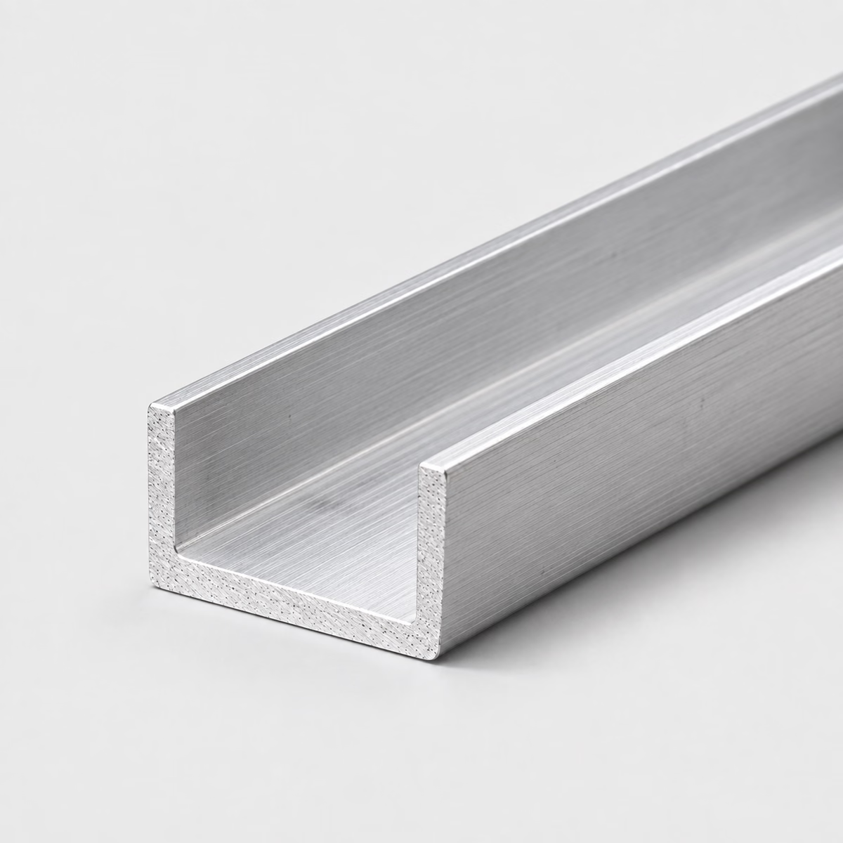
ALUMINUM / CHANNELIllustrative material image
LIVE DIMENSION VIEWCHANNEL
Aluminum Channel
See your specification take shape.
Dimension labels are on. Enter dimensions to see their labels.
MADE FOR YOUR CUT LIST
The right metal. Your exact dimensions.
From a single part to a mixed-material project. Configure each cut, then bring it all together in one reviewed quote.
Custom cut sizesMultiple parts, one requestReviewed specifications
CUT-TO-SIZE METAL
Aluminum Channel
Specify aluminum channel with a 6061 or 6063 reference, flange width, outside height and thickness. Include a section drawing when internal clearance matters.
Attach a PDF, DXF or STEP file. You can request a review without configuring individual pieces.
How your quote works +
Add one or more cuts, share your requirements and tell us where to deliver. We review material, cutting and freight before sending a quote.
Dimensions & material weight +
Dimensions describe your requested section and cut length. Standard sections and feasible cuts are confirmed during review. Include any tolerance in project details. Weight is theoretical, uses ideal section geometry and excludes corner radii, packaging and cutting loss. The preview is a schematic, not a manufacturing drawing.
PROJECT CONTENTS
Your cut list
Cut lines are saved in this browser. Only added pieces are included in your request.
What to include in your request
The builder assumes uniform thickness. A track, slot or mating insert may need a more detailed section than the preview can show.
Material
Aluminum
Profile
Channel
Grade references
6061 / 6063 — confirm grade and condition in the quote
Subject to review; no live-stock or tolerance guarantee
Ideal uniform-thickness section. Weight excludes root radii, tapered flanges and tolerances. Requested dimensions do not imply arbitrary sections can be manufactured.
01
An opening can provide clearance, access or guidance
A channel around a panel edge needs a different description from a channel guiding a moving insert. The surround may primarily cover an edge; the guide needs defined contact, clearance and alignment along its engagement. A mounting channel may use the opening simply to admit a tool or fastener. These roles explain why the same nominal section can lead to different acceptance requirements. The component inside or beside the channel provides the context for understanding what the web and flanges actually do.
02
The web, flanges and opening are distinct working areas
The web connects the two flanges and forms the back of the channel. A hole in that web differs from one in a flange, both in position and in how it can be reached during assembly. The opening has its own surface and corner requirements if another part enters it. Exterior finishing does not define those internal interfaces. Keeping the working areas distinct clarifies a channel specification, particularly when an exposed outside face and a hidden sliding or locating surface need different treatment.
03
Compare access with enclosure
Compare channel with rectangular tube when the design needs a closed member, and with angle when only one side flange is necessary. A flat bar may be sufficient if the proposed channel is functioning only as a mounting strip. Each alternative changes the mounting faces, access and surrounding envelope, so include the assembled relationship when considering it. A track or guide also needs its own fit and alignment requirements; the profile name and the theoretical section preview cannot establish moving-part performance.
Compare aluminum sections around a component
Compare aluminum sections around a component
Catalog choice
Useful starting point
Access or fit question
Aluminum channel
An open-sided surround or member
Inside opening and locating surfaces
Aluminum rectangular tube
A closed surrounding section
End access and connector envelope
Aluminum angle
One corner or side support
Whether a second flange is needed
PUT THE DIMENSIONS INTO PRACTICE
Example: a four-piece channel request
Use this illustrative cut line to see how the fields work. It is a dimensional example, not a stock listing or a recommended section for a particular load.
Flange width1 in25.4 mm
Outside height2 in50.8 mm
Uniform thickness0.125 in3.175 mm
Cut length24 in609.6 mm
The model uses a 2 in outside height, 1 in flange width and 1/8 in uniform thickness. Its ideal area is t × (2b + h − 2t), or 0.46875 square inches. A channel with tapered flanges or a different web thickness requires its actual section data.
How the theoretical weight is calculated
Cross-sectional area × cut length × reference density = estimated material weight.
Material in this example
Aluminum
Reference for this example
6061 grade reference
Density used
2,700 kg/m³
One piece, approximately
1.10 lb / 0.50 kg
Four pieces, approximately
4.39 lb / 1.99 kg
Calculated from ideal geometry and a reference density. Actual section, alloy, tolerances, cutting loss and packaging can change the result. This is not a shipping weight or a load rating.
On your own cut list, add a part reference and quantity to each distinct size. Put extra operations such as holes, miters, threads or finish work on the drawing, then keep that drawing reference with the relevant line.
Can I use aluminum channel as a close-fitting track?
Specify the clear opening, internal radii, straightness and required clearance for the moving part. Outside dimensions alone do not establish a usable sliding fit.
Is the channel wall the same thickness everywhere?
That is the simplified model used by the configurator, not a promise about every available extrusion. Attach the actual section if web and flange thicknesses differ.
Does requesting an unusual channel create a custom extrusion?
No. The request is reviewed for sourcing and fabrication. New extrusion tooling or custom production would need separate scope confirmation.
How does a channel guide differ from an edge surround?
A guide controls a moving or locating relationship through contact, clearance and alignment. An edge surround may only cover or retain a perimeter. The same nominal opening can serve either role, but the guide requires a more complete definition of its working surfaces and engagement.
What are the web and flanges of a channel?
The web forms the connecting back, and the flanges form the sides of the opening. Distinguishing them makes hole and finish descriptions clearer. A web hole and a flange hole can have different tool-access and attachment relationships even when their diameters are identical.
Can only the exterior of a channel receive a cosmetic finish requirement?
Yes. Identify the exterior faces and state the expectations for the opening and cut ends separately. If the inside will also be visible after installation, show that condition. A general polished or anodized note can otherwise leave the intended surface coverage unclear.
How do I specify two channels that face each other?
Provide an assembly section showing their separation, orientation and the component between them. Identify the surfaces that control the gap and any alignment requirements along the length. Ordering two equal channels does not establish their installed spacing or their relationship to a moving insert.
Why is useful opening length different from overall assembly length?
End stops, caps or attached brackets can occupy space beyond or within the channel body. The length available to a panel or insert therefore may not match the assembly envelope. Separating those dimensions clarifies what the raw channel provides and what the added components do.
What information helps compare a channel with a fabricated bracket?
Provide the finished assembly drawing and identify which dimensions, mounting faces and openings must remain unchanged. List the allowable differences in joints or appearance. Comparing those requirements is more useful than treating two similar outside envelopes as equivalent finished components.
What dimensions do I need to request aluminum channel?
Provide flange width, outside height, uniform thickness, cut length, plus quantity for each size. Use inches or millimeters consistently. Add the required grade, condition, finish and any critical tolerances; attach a drawing for details the standard fields cannot describe.
Turn your specification into a clear request.
Include the material, dimensions, quantity and critical requirements. Availability, supplied condition, cutting and delivery are confirmed in a reviewed quote.