Add it to your cut list, or continue with the pieces and files already included.
CUT TO YOUR DIMENSIONS
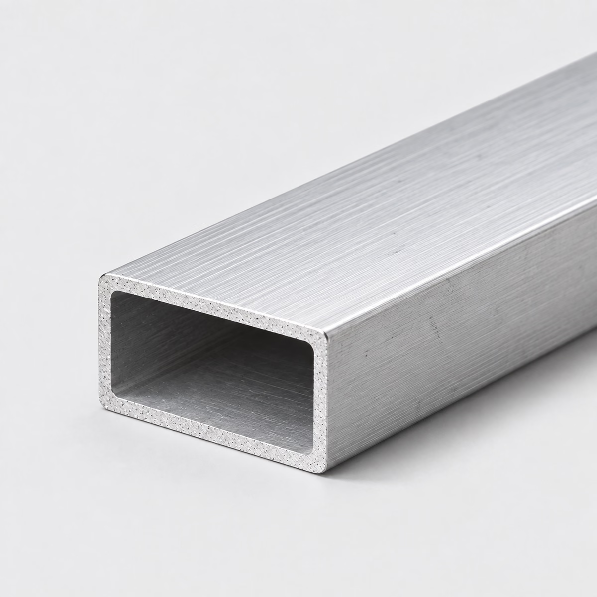
ALUMINUM / RECTANGULAR TUBEIllustrative material image
LIVE DIMENSION VIEWRECTANGULAR TUBE
Aluminum Rectangular Tube
See your specification take shape.
Dimension labels are on. Enter dimensions to see their labels.
MADE FOR YOUR CUT LIST
The right metal. Your exact dimensions.
From a single part to a mixed-material project. Configure each cut, then bring it all together in one reviewed quote.
Custom cut sizesMultiple parts, one requestReviewed specifications
CUT-TO-SIZE METAL
Aluminum Rectangular Tube
Specify aluminum rectangular tube by outside width, height, wall and length. Add the 6061 or 6063 reference, installed orientation and any end-cut drawing.
Attach a PDF, DXF or STEP file. You can request a review without configuring individual pieces.
How your quote works +
Add one or more cuts, share your requirements and tell us where to deliver. We review material, cutting and freight before sending a quote.
Dimensions & material weight +
Dimensions describe your requested section and cut length. Standard sections and feasible cuts are confirmed during review. Include any tolerance in project details. Weight is theoretical, uses ideal section geometry and excludes corner radii, packaging and cutting loss. The preview is a schematic, not a manufacturing drawing.
PROJECT CONTENTS
Your cut list
Cut lines are saved in this browser. Only added pieces are included in your request.
What to include in your request
Label width and height consistently with the drawing. Include which face carries holes, joints or a visible finish.
Material
Aluminum
Profile
Rectangular Tube
Grade references
6061 / 6063 — confirm grade and condition in the quote
Subject to review; no live-stock or tolerance guarantee
Outside dimensions and uniform wall. Theoretical weight excludes corner radii, welds and tolerances. Supplier section review is required.
01
Broad and narrow faces create an installed orientation
Rectangular tube has unequal outside dimensions, so rotating the section changes the face presented to a bracket or panel. A hole pattern that fits the broad face may not serve the same layout on the narrow face. In an equipment surround, that distinction is part of the component identity rather than merely a choice of dimension labels. An end view tied to the installed position makes the relationship visible and separates similar members that use the same stock section in different orientations.
02
A corner joint combines length, angle and face direction
At an angled end, the long point, short point and centerline are different measurement references. An overall length therefore needs a convention before it can describe a mitered member unambiguously. A frame corner also joins particular broad or narrow faces, which determines how the surfaces meet and which transitions remain visible. Showing the two members together makes those choices easier to understand. The stock cut, finished joint and cosmetic treatment are related decisions, but they are not the same operation or acceptance requirement.
03
Compare the full section, not one dimension
A square tube, rectangular tube and channel may share one outside dimension but serve different layouts. Compare available mounting faces, internal access and the envelope occupied by the entire section. An open channel may suit a component that must be inserted from the side, while a flat bar may suit a simple strap without a hollow section. Keep structural selection separate from the catalog preview: the design must establish the required member and its orientation before purchasing dimensions can be finalized.
Compare profiles by envelope and access
Compare profiles by envelope and access
Catalog choice
Useful starting point
Detail to keep explicit
Aluminum rectangular tube
Closed section with unequal sides
Broad-face orientation
Aluminum square tube
Closed section with equal sides
Outside envelope and connections
Aluminum channel
A section with an accessible opening
Inside opening and attached hardware
PUT THE DIMENSIONS INTO PRACTICE
Example: a four-piece rectangular tube request
Use this illustrative cut line to see how the fields work. It is a dimensional example, not a stock listing or a recommended section for a particular load.
Outside width2 in50.8 mm
Outside height1 in25.4 mm
Wall thickness0.125 in3.175 mm
Cut length24 in609.6 mm
The outside section is 2 × 1 in with a 1/8 in wall. Subtracting two walls gives an ideal 1.75 × 0.75 in internal rectangle. This ignores rounded corners and any seam; use it to understand the fields, not as a guaranteed clearance envelope.
How the theoretical weight is calculated
Cross-sectional area × cut length × reference density = estimated material weight.
Material in this example
Aluminum
Reference for this example
6061 grade reference
Density used
2,700 kg/m³
One piece, approximately
1.61 lb / 0.73 kg
Four pieces, approximately
6.44 lb / 2.92 kg
Calculated from ideal geometry and a reference density. Actual section, alloy, tolerances, cutting loss and packaging can change the result. This is not a shipping weight or a load rating.
On your own cut list, add a part reference and quantity to each distinct size. Put extra operations such as holes, miters, threads or finish work on the drawing, then keep that drawing reference with the relevant line.
Does it matter which way rectangular aluminum tube is installed?
Yes. The orientation affects assembly geometry and bending behavior. Identify the installed position on the drawing rather than treating width and height as interchangeable labels.
Can the configurator describe mitered ends?
The length fields alone do not define a miter. Attach the angle, long-point or short-point convention, orientation and quantity for review.
Can I order a custom wall with any outside dimensions?
You can record the section you need reviewed. The entry does not establish that a standard extrusion exists or that tooling for a new extrusion is included.
Why does rotating rectangular tube change a panel connection?
Rotation changes whether the broad or narrow face meets the panel and its bracket. The available face width and the surrounding envelope therefore change together. A hole layout that works in one orientation should be checked in the installed assembly before being carried into the other.
What information is needed for a rail with an attached panel?
Show the panel envelope, fixing locations and the face of the tube used for attachment. Include the required spacing from neighboring components. This allows the tube request and panel drawing to be read together instead of treating the rail as an isolated rectangular member.
What is the difference between long-point and short-point cut length?
They refer to different ends of an angled cut: the farther tip and the nearer tip relative to a stated reference. The values are not interchangeable. A mitered member needs a clear measurement convention so its length describes the intended corner geometry.
Why can a closed tube complicate an internal bolted connection?
The enclosed center limits the routes for positioning and reaching hardware compared with an open section. The connection needs an assembly method, such as a defined access opening or separate insert arrangement. A hole in one wall does not by itself explain how the mating hardware is installed.
How do I describe a tube that must accept a rectangular insert?
Provide the insert's required envelope, insertion length and clearance, including its corner geometry. Identify whether fit is required through the entire member or only near the end. The nominal outside dimensions and wall do not fully describe the internal mating relationship.
Should visible corner joints be included in the finish description?
Yes. Mark which faces meet at each corner and describe the expected appearance of the assembled joint. Separate that requirement from the finish on an unjoined tube length. A consistent surface on individual members does not by itself define how the finished corner should look.
What dimensions do I need to request aluminum rectangular tube?
Provide outside width, outside height, wall thickness, cut length, plus quantity for each size. Use inches or millimeters consistently. Add the required grade, condition, finish and any critical tolerances; attach a drawing for details the standard fields cannot describe.
Turn your specification into a clear request.
Include the material, dimensions, quantity and critical requirements. Availability, supplied condition, cutting and delivery are confirmed in a reviewed quote.